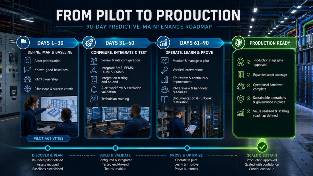
A predictive-maintenance pilot becomes operational only when asset priorities, baselines, alert rules, work-order routing and verified outcomes are placed under one accountable rollout plan.
The technology is not the implementation plan
By this stage of the series, the technical components are clear. Vibration monitoring detects mechanical degradation. Thermal imaging identifies deteriorating electrical connections. Impedance trending reveals battery-cell drift. Water-quality and approach-temperature trends expose cooling-tower performance risk. CMMS and DCIM integration converts credible warnings into owned maintenance actions.
The remaining challenge is execution.
Many predictive-maintenance initiatives begin with a sensor purchase or vendor demonstration. A few assets are connected, dashboards appear and early anomalies generate interest. The program then stalls because the organization has not agreed on ownership, acceptance criteria, response procedures or what constitutes a successful pilot.
A production-ready program requires more than working sensors. It needs:
- A defined asset and failure-mode scope
- Known-good baselines
- Approved validation and prioritization rules
- Clear operational ownership
- CMMS and DCIM integration
- Tested maintenance procedures
- Trained responders
- Evidence-based closure
- Measurable stage-gate criteria
A 90-day roadmap creates enough structure to prove the control loop without trying to instrument the entire facility at once.
Start with a bounded pilot
The first rollout should not cover every maintainable asset. It should cover a small group of critical assets where the failure modes, available evidence and operational consequences are sufficiently understood.
A balanced AI data-center pilot might include:
- One UPS battery string for impedance trending
- One critical PDU or transfer/tie switch for thermal and contact-resistance monitoring
- One chiller and associated pump for vibration and fluid-condition trending
- One fan wall unit at individual-module level
- One cooling-tower cell for approach-temperature and basin-water monitoring
This provides exposure to electrical, mechanical, cooling and control-system integration without allowing the pilot to become unmanageable.
Asset selection should consider:
- Failure consequence
- Existing redundancy
- Failure frequency or known degradation history
- Availability of measurable leading indicators
- Availability of a known-good baseline
- Ability to intervene safely
- Ability to verify the outcome
- Availability of an accountable owner
The objective is not to choose the assets with the most sensors. It is to choose assets where the complete detect–validate–act–verify loop can be demonstrated.
Days 1–30: define, map and baseline
The first 30 days establish the foundation. No automated work-order creation should begin until the asset structure, evidence requirements and responsibilities are agreed.
Confirm the pilot charter
The pilot charter should define:
- Business and operational objectives
- Included assets and failure modes
- Explicit exclusions
- Pilot start and end dates
- Budget and approved resources
- Required system integrations
- Success criteria
- Governance and reporting cadence
- Conditions that would pause the pilot
- Production-expansion decision authority
A suitable objective is not “install predictive sensors.” A stronger objective is to demonstrate that validated condition evidence from selected critical MEP assets can be converted into owned maintenance work and verified closure with an acceptable false-positive rate and no unapproved operational risk.
Build the asset and failure-mode register
Each pilot asset should be mapped to the exact component and measurement point being monitored.
- Asset and component identifier
- Equipment type and location
- Served system, hall, row or load
- Failure mode
- Expected warning signature
- Primary sensor or inspection method
- Corroborating evidence
- Criticality and redundancy
- Owner and OEM/vendor support
- Applicable procedure and CMMS reference
The monitoring granularity must match the failure mode. Monitoring an FWU only at array level, or registering a PDU without identifying the exact joint or terminal, prevents consistent trending and ownership.
Capture known-good baselines
Baselines should be captured when the equipment is confirmed healthy, preferably at commissioning or after verified major service. Record operating load, speed or command, environmental conditions, measurement point, instrument and method, configuration, relevant setpoints, supporting inspection evidence and approval status.
Generic thresholds may support protection or initial screening, but predictive trending depends on comparison with the same equipment under comparable conditions.
Establish the RACI
The pilot needs explicit ownership across operations, maintenance, reliability engineering, controls, DCIM, CMMS, IT/OT integration, OEM/vendor support, finance/risk and the program sponsor. If everyone is supporting but nobody is accountable, the pilot will produce observations without decisions.
Days 31–60: configure, integrate and test
The second phase builds the operational control loop.
Configure validation rules
Every condition rule should define the source platform, asset and failure mode, baseline or criterion, persistence requirement, operating context, data-quality requirement, corroboration, deduplication window, maintenance suppression, confidence, consequence, urgency, routing outcome and response owner.
Not every observation should create a work order. Some should create a validation task, update an existing event or remain as trend evidence.
Configure alarm-fatigue controls
Before production use, test duplicate-event suppression, persistence timers, maintenance windows, sensor-quality flags, stale-data detection, event correlation, escalation, time synchronization, communication-loss behavior and audit history.
A degraded FWU module might create airflow, vibration, motor-temperature and rack-inlet alarms. The integration should correlate them into one condition event rather than four unrelated work orders.
Build and test the CMMS workflow
Predictive work orders should carry the asset, failure mode, current condition and baseline, rate of change, operating context, corroborating evidence, confidence, consequence, affected service, redundancy, procedure, safety controls, parts and labor requirements, retest method and acceptance criteria.
Test the entire chain: source event, asset mapping, DCIM context, suppression, deduplication, priority, CMMS routing, notification, escalation, evidence access and retest-gated closure. Testing only the sensor-to-dashboard path is insufficient.
Train teams using real scenarios
Operations should practise validating context, checking redundancy, applying immediate controls and escalating credible conditions. Maintenance should practise reading evidence, selecting procedures, planning resources, documenting work and performing comparable retesting. Reliability and integration teams should practise false-positive review, mapping correction and approved baseline resets.
Include at least one false-positive scenario, one duplicate-alarm scenario and one high-consequence condition with reduced redundancy.
Days 61–90: operate, learn and prove
The final phase runs the pilot under controlled production conditions.
Operate with daily visibility
During the first production weeks, review new observations, events awaiting validation, suppressed and deduplicated alerts, high-priority conditions, work awaiting assignment or parts, repairs awaiting retesting, data-quality failures and open decisions. This is an early-life control, not necessarily a permanent daily meeting.
Review every intervention as a complete case
Each intervention should preserve the original condition, baseline comparison, validation decision, priority rationale, work order, corrective action, retest result, acceptance decision, baseline-reset decision, financial classification and rule lesson.
A work order completed without retesting should remain open or conditionally monitored. It should not be counted as a successful predictive intervention.
Measure operational performance
Track raw alerts, suppressed and deduplicated alerts, invalid observations, validated events, actionable-alert rate, detection-to-validation time, validation-to-assignment time, high-priority ownership, planned versus emergency interventions, retest compliance, repeat-alert rate, false-positive cost, pre-impact detections and data availability.
A successful pilot does not necessarily generate many work orders. It generates an appropriate number of high-confidence actions and demonstrates that non-actionable noise is controlled.
Use stage gates instead of one final presentation
Gate 1: baseline readiness
- Assets and failure modes are approved
- Measurement points are mapped
- Owners are assigned
- Baselines are approved or scheduled
- Data sources and system access are available
- Safety and operating procedures exist
Gate 2: integration readiness
- Validation rules are documented
- Suppression and deduplication are tested
- Asset and service mappings are correct
- CMMS routing and escalation paths work
- Training and scenario exercises are completed
Gate 3: production-expansion readiness
- Data quality is acceptable
- False positives are understood and controlled
- Critical events receive timely ownership
- Work orders contain usable evidence
- Retesting and closure controls operate
- No unresolved safety or operational risks remain
- Cost and benefit assumptions are documented
- A sustainable support model exists
Passing a technology demonstration is not the same as passing a production-readiness gate.
Decide what scales—and what does not
At day 90, each pilot rule should receive one of four decisions:
- Scale: evidence quality, workflow and value justify wider deployment.
- Continue pilot: promising result, but more events or operating conditions are needed.
- Redesign: failure-mode logic, sensor coverage, mapping or workflow requires correction.
- Retire: the rule does not produce enough actionable value to justify its cost or complexity.
A retired rule is not necessarily a failed pilot. Identifying an expensive, low-value monitoring approach before fleet-wide rollout is itself useful.
Put this into practice
Download the AI Hyperscale 90-Day Predictive-Maintenance Implementation Roadmap to prioritize assets and failure modes, assign RACI ownership, track baseline and sensor readiness, test integrations and alert rules, manage training and pilot interventions, control risks and decisions, and complete the three production stage gates.
A biblical perspective on committed planning
“Commit to the Lord whatever you do, and he will establish your plans.”
Proverbs 16:3 (NIV)
A sound implementation plan combines commitment with disciplined execution. Committing the work to God does not remove the need for preparation, accountability or wise decisions. It places the purpose and responsibility of the work in the right order. A predictive-maintenance rollout should therefore be planned carefully, carried out faithfully and reviewed honestly, with stewardship of people, equipment and operational risk at its center.
The production standard
A predictive-maintenance program is ready for production when it can repeatedly demonstrate one controlled sequence:
detect a credible condition, validate it in context, assign an accountable response, complete approved work, retest the original evidence and use the outcome to improve the next decision.
The first 90 days should prove that sequence on a bounded set of critical assets. Scaling comes afterward—not because the technology looks impressive, but because the operating model has shown that it can protect uptime without creating new noise, unmanaged work or hidden risk.

