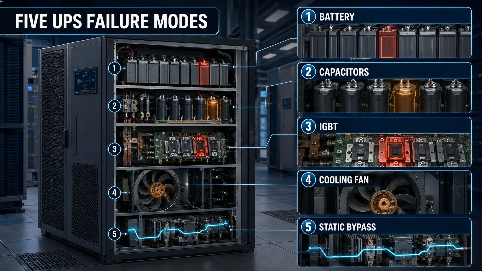
Capacitor drift, IGBT thermal fatigue, and battery cell imbalance rarely show up on a runtime test until it’s too late.
Why “UPS failure” isn’t one thing
A UPS trip or failure gets logged as a single event, but the root cause is almost always one of a small set of recurring failure modes — each with its own warning signature, its own timeline, and its own monitoring approach. Treating “UPS failure” as a single risk to manage against leads to generic monitoring; treating it as five distinct failure modes leads to monitoring that actually catches the problem developing.
1. Battery cell degradation and imbalance
Covered in depth in the previous post in this series — but worth restating here as the most common single cause of UPS-related incidents in practice. A string with unmonitored cell-level degradation can pass every scheduled runtime test right up until the moment a real discharge event exposes the weak cells, at which point the string underperforms exactly when it’s needed. Impedance trending per cell is the leading indicator; a pass/fail runtime test is not.
2. Capacitor drift
DC bus and filter capacitors in UPS power electronics degrade with heat and time — electrolyte dries out, capacitance drops, and equivalent series resistance (ESR) rises. This is a slow, predictable failure mode in terms of mechanism, but it accelerates sharply once a capacitor crosses a certain age or thermal exposure threshold. Capacitance and ESR testing during scheduled maintenance windows, combined with thermal imaging to catch capacitors running hotter than their baseline, are the two signals that catch this before it causes a fault.
3. IGBT thermal fatigue
Insulated-gate bipolar transistors (IGBTs) in the UPS inverter and rectifier stages are subjected to repeated thermal cycling every time load changes. Over enough cycles, this causes fatigue at the solder joints and bond wires inside the device — a mechanical failure mode driven by electrical and thermal cycling rather than a single overload event. Thermal imaging during operation, watching for IGBTs running hotter than sibling devices under the same load, is the primary way to catch this developing before a hard failure.
4. Cooling fan and fan bearing wear
UPS units rely on internal cooling fans to manage the heat generated by the power electronics, and those fans are mechanical components subject to the same bearing wear as any other rotating equipment. A degraded internal fan reduces cooling effectiveness, which accelerates capacitor drift and IGBT thermal fatigue simultaneously — making this a failure mode that compounds the other two if it goes undetected. Vibration and airflow monitoring on internal fans, not just external cooling infrastructure, catches this early.
5. Static bypass switch failure
The static bypass switch is the component that transfers load to utility power if the UPS itself faults — which means it’s a component that may sit idle for long periods and is only truly tested during an actual fault event or a scheduled transfer test. Silicon-controlled rectifiers (SCRs) in the bypass path can degrade without showing symptoms during normal operation, since normal operation never routes current through them. Scheduled transfer testing combined with thermal imaging of the bypass path during those tests is the only reliable way to catch degradation here, since there’s no passive monitoring signal available while the switch sits idle.
The pattern across all five
Four of these five failure modes share a common trait: they’re invisible during normal operation and only become apparent under the specific stress condition that exposes them — a real discharge, a load transient, an actual bypass event. That’s exactly why waiting for a symptom during normal operation is not a viable detection strategy for UPS failure modes, and why the combination of impedance trending, thermal imaging, and scheduled transfer testing exists as a set rather than a single tool.
Put this into practice: Download the AI Hyperscale UPS Five Failure Modes Register to map each UPS subsystem to its applicable failure modes, document monitoring and test evidence, schedule dormant-path testing, prioritize findings, assign work orders, and verify closure through retesting.
Next in this series
The next post shifts to chillers and pumps, where the equivalent failure modes are mechanical rather than electrical — but the same principle holds: the failure signature is visible in trend data well before it’s visible in performance.

